|
|
Post by nick robinson on Dec 20, 2007 11:13:20 GMT
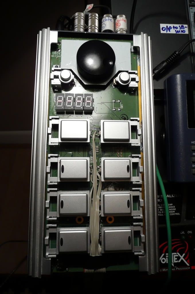
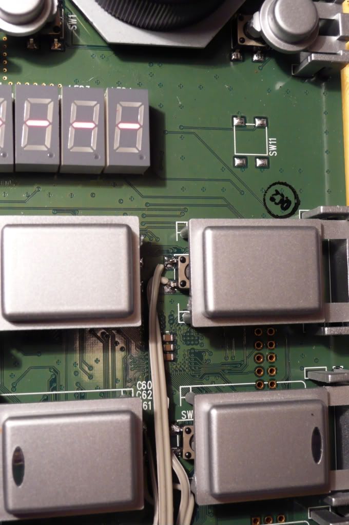
thaks for the photos of your rewire job Stephen. You have two cables running from each switch - is there not a shared earth? That way you only need one lead for each switch plus an earth?
|
|
|
|
Post by Stephen Scott on Dec 20, 2007 11:55:48 GMT
thaks for the photos of your rewire job Stephen. You have two cables running from each switch - is there not a shared earth? That way you only need one lead for each switch plus an earth? I didn't occur to me to check this ! If this is so, you could use a neater cable / multipin arrangement than I did. You should open it up and check it. |
|
|
|
Post by nick robinson on Dec 20, 2007 18:10:10 GMT
I didn't occur to me to check this ! If this is so, you could use a neater cable / multipin arrangement than I did. You should open it up and check it. I'll go into autopsy mode over xmas ;D I also wondered if this could be hotwired to switch a loop (or other fx) on & off by crossing though the beam with the guitar neck (or other protruberence) ? www.maplin.co.uk/Module.aspx?ModuleNo=37770&doy=20m12&C=SO&U=strat15I'm dead keen to find a cheap alternative to the D beam - wonder if Xavier could produce one? |
|
|
|
Post by andybutler on Dec 21, 2007 9:26:34 GMT
|
|
|
|
Post by nick robinson on Dec 21, 2007 13:50:09 GMT
I didn't occur to me to check this ! If this is so, you could use a neater cable / multipin arrangement than I did. You should open it up and check it. Have done with inconclusive results - I suspect not is the answer. |
|
|
|
Post by Stephen Scott on Oct 27, 2009 18:53:33 GMT
Hi Stephan, I took the original pics, but I think I've now lost them following a recent HD crash. I wonder if Nick has copies?
Once you open up the box of the soundbite, it's really quite obvious what you need to do. You just need to connect wires to each switch contact (2 per switch) and work out some way of bringing the leads to the outside world - I used a ribbon cable which passes through the chassis quite easily, but I read of someone (Michael Una, I believe) who fitted a D-connector into the casing. I considered this, but the casing is really tough to cut, and would've been difficult.
The 2 most difficult things about this project are (1) you need a tiny soldering iron tip and a very steady hand to solder wires onto the original switch contacts, and (2) you have to be very careful to neatly lay the wires inside the casing so as to avoid impeding the movement of the original switches (I find it handy to have the option to use either footswitches or case switches). That said, overall, it's not particularly tricky provided you can plan and take care.
I guess I could open up my Soundbite and take a few more snaps if it's really important to you. Let me know.
Stephen
|
|
|
|
Post by Stephen Scott on Oct 28, 2009 20:18:49 GMT
I found the pics. Hope they help. btw, why do you prefer the micro?   |
|
|
|
Post by Stephen Scott on Oct 30, 2009 16:10:26 GMT
The more I think, the more I know I need to embed my Soundbite micro in a custom 6 switch foot controller. do it, DO IT! |
|
james60
Melos Echo Chamber

Posts: 1
|
Post by james60 on Dec 9, 2009 0:59:01 GMT
Hello Loopers.
I have a Grabber and have thought about this mod for years. I think I learned of it from a Stephen Scott post somewhere. Are the momentary stomp switches of the normally open or normally closed type? Has anyone brought the three way switch on the bottom out to a switch(s)? Any thougthts on how this would be wired? Having reverse on a stomp would be nice. Peace
|
|
|
|
Post by Stephen Scott on Dec 11, 2009 10:49:20 GMT
James, the footswitches I used are normally open. I used these, which have quite a nice action, and seem quite robust; www.maplin.co.uk/Module.aspx?ModuleNo=34489I haven't thought about putting the little slide switch onto a footswitch, but I'm sure it wouldn't be difficult. Stephen |
|